MyDriveWorks - Tech Tips
This demonstrates how each different DriveWorks 3D Mode works with a Project and comparison.
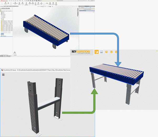
Mixed Mode is an implementation method for DriveWorks 3D. Mixed Mode is the combination of a SOLIDWORKS & DriveWorks Autopilot 3D Preview and Static DriveWorks 3D files.
The idea of this method is that complex geometry is generated through SOLIDWORKS and simple standard components are saved as static 3D files. The two are then combined in a DriveWorks 3D Document and assembled together to create the final assembly.

In this example, the legs of the Conveyor only change in Height and Width. There are about 50 variations of legs that can be added to the Conveyor. Each permutation has been created and saved as a DriveWorks 3D File.
The Conveyor Bed is different. This changes in Length, Width, Quantity of Rollers and Side Rails. This model is a little more complex. This can be generated through SOLIDWORKS and DriveWorks Autopilot and combined in a DriveWorks 3D Document.
The DriveWorks User Form requires a 3D Preview Box Control, a Macro Button and any other Controls necessary to drive the SOLIDWORKS Model.
SOLIDWORKS and DriveWorks Autopilot are also required to be setup to run 3D Previews. The following topics explain how to do this:
How To: Troubleshoot Autopilot 3D Preview
Below are the order of events that are carried out to make Mixed Mode possible in DriveWorks.
This demonstrates how each different DriveWorks 3D Mode works with a Project and comparison.
View all available MyDriveWorks Tech Tips.