Sheet Metal Features
This document describes the types of rules that can be applied to models that have advanced feature parameters captured.
Driving advanced feature dimensions increases model generation time. Where possible capture feature dimensions (distances, numbers and angles) as dimensions rather than an advanced feature parameter.
During model generation captured dimensions are driven before captured advanced feature parameters. If the advanced feature parameter has also been captured as a dimension the value being driven into the advanced feature parameter will override the captured dimension.
Bend Table
| Parameter | Input Type | Description |
|---|---|---|
| Bend Table File Path | Path | Sets file path for the bend table. |
The result is required to be a full path, file name and extension to the table to use for the Bend Table.
Mapped network and UNC paths are supported, for example:
Mapped
"E:\DriveWorks\SheetMetal\Bend Table 2.xlsx"
UNC
"\\COMP-NAME\DriveWorks\SheetMetal\Bend Table 2.xlsx"
Base Flange
| Parameter | Input Type | Description |
|---|---|---|
| Bend Allowance | Number | Sets the value of the bend allowance |
| Bend Deduction | Number | Sets the value of the bend deduction |
| Bend Radius | Number | Controls the bend radius for a sheet metal feature |
| K Factor | Number | Sets the K-Factor |
| Relief Ratio | Number | Controls the thickness for a sheet metal feature |
| Thickness | Number | Controls the thickness for a sheet metal feature |
| Type | One of the following values:
| Sets the bend allowance type |
Break Corner
| Parameter | Input Type | Description |
|---|---|---|
| Break Type | One of the following values:
| Sets the type of break to use. |
| Distance | Number
Must use the SOLIDWORKS Document Units. | Sets the chamfer length or fillet radius, depending on the break type. |
Edge Flange
| Parameter | Type | Description |
|---|---|---|
| Auto Relief Type | One of the following values:
| Sets the auto-relief type for this edge flange.
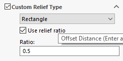
To ensure Auto Relief Type drives correctly please make sure that Custom Relief Type is checked in the master file. CustomReliefTypeSW
|
| Custom Bend Allowance Type | One of the following values:
| Sets the bend allowance type |
| Offset DimType | One of the following values:
| Sets the offset dimension type for this edge flange |
| Offset Type | One of the following values:
| Sets the offset type for this edge flange |
| Position Type | One of the following values:
| Sets the Position type for this edge flange |
| Relief Tear Type | One of the following values:
| Sets the type of relief tear for this edge flange feature |
Gusset
| Parameter | Input Type | Description |
|---|---|---|
| Offset Distance | Distance | Set the distance of the offset. |
| Flip Offset | True or False | Reverses the direction of the offset. |
| Profile Dimension Scheme | One of the following values:
| Sets the dimension scheme to use.
0 will use the value of the Indent Depth property. 1 will use the values of the Profile Length and Profile Height or Profile Angle properties. |
| Indent Depth | Distance | Defines a symmetrical gusset profile using a single depth dimension. |
| Profile Length (d1) | Distance | Specifies a linear value from the inside of the sheet metal part to the point on the x axis where the gusset intersects the sheet metal body. |
| Use Angle Dimension for Profile | True or False | True to use the Profile Angle parameter, False to use the Profile Height parameter. |
| Profile Height (d2) | Distance | Specifies a linear value from the inside of the sheet metal part to the point on the y axis where the gusset intersects the sheet metal body. |
| Profile Angle (a1) | Angle | Creates the section profile of the gusset based on the Profile Length parameter and the angle. |
| Gusset Type | One of the following values:
| 0 creates a gusset with a rounded edge.
1 creates a gusset with a flat edge. |
| Fillet Gusset Edges | True or False | Gusset Type must be Flat (1).
True to apply a fillet to the flat gusset edges. |
| Edge Fillet Radius | Radius | Gusset Type must be Flat (1).
Sets the radius of the flat gusset fillet. |
| Indent Width | Distance | Sets the gusset width. |
| Indent Thickness | Distance | Set the wall thickness of the gusset |
| Draft Side Faces | True or False | True to apply a draft to the gusset. |
| Draft Angle | Angle | Sets the draft angle to apply to the gusset.
Draft Side Faces must be True. |
| Fillet Inner Corners | True or False | True to set if the inner side of the gusset is filleted. |
| Inner Corner Fillet Radius | Radius | Sets the radius of the inner corner fillet.
Fillet Inner Corners must be True. |
| Fillet Outer Corners | True or False | True to set if the outer side of the gusset is filleted. |
| Outer Corner Fillet Radius | Radius | Sets the radius of the outer corner fillet.
Fillet Outer Corners must be True. |
Hem
| Parameter | Input Type | Description |
|---|---|---|
| Angle | Number | Sets the hem size angle.
Bend Type must be set to Tear Drop or Rolled |
| Bend Position | One of the following values:
| Sets the bend position. |
| Gap Distance | Number | Sets the gap distance.
Bend Type must be set to Open. |
| Bend Table File | The name of the bend table file. | Full path, file name and extension to the table to use for the Bend Table.
Mapped network and UNC paths are supported, for example:
CustomBendAllowance must be set to Bend Table |
| Bend Deduction | Number | Sets the bend deduction.
CustomBendAllowance must be set to Bend Deduction |
| Bend Allowance | Number | Sets the bend allowance.
CustomBendAllowance must be set to Bend Allowance |
| K Factor | Number | Sets the K factor.
CustomBendAllowance must be set to K Factor |
| CustomBend
Allowance Type | One of the following values:
| Sets the custom bend allowance to use. |
| Bend Type | One of the following values:
| Sets the type of Hem to apply. |
| Length | Number | Sets the length.
Bend Type must be set to Closed or Open. |
| Miter Gap | Number | Sets the miter gap for intersecting hems. |
| Radius | Number | Sets the hem radius
Bend Type must be set to Tear Drop or Rolled. |
| ReverseDirection | True or False | True to reverse the hem direction
False to preserve the direction. |
Jog
| Parameter | Input Type | Description |
|---|---|---|
| Jog Position | One of the following values:
| Sets the jog position type for the Jog feature.
Select from the following numeric values: 1 = BendCenterLine 2 = MaterialInside 3 = MaterialOutside 4 = BendOutside |
| Offset Distance | Number | Sets the value of the Jog Offset. |
| Bend Radius | Number | Sets the bend radius for the Jog feature. |
| FixProjectedLength | True or False | Sets whether to fix the projected length for the Jog feature. |
| JogAngle | Number | Sets the jog angle for the Jog feature. |
| Reverse Direction | True or False | Sets whether to reverse the direction of the Jog feature. |
| Reverse Offset | True or False | Sets whether to reverse the offset of the Jog feature. |
| Use Default Bend Allowance | True or False | Sets whether to use the default bend allowance for the Jog feature. |
| Use Default Bend Radius | True or False | Sets whether to use the default bend radius for the Jog feature. |
Miter Flange
| Parameter | Input Type | Description |
|---|---|---|
| Bend Allowance | Distance | Sets the value of the bend allowance. |
| Bend Deduction | Distance | Sets the value of the bend deduction. |
| Bend Radius | Distance | Sets the bend radius of the miter flange.
Ensure Use Default Radius is set to False in the master model before you drive the bend radius. |
| Custom Bend Allowance Type | One of the following values:
| Sets the bend allowance type. |
| End Offset | Distance | Sets the end offset for the miter flange. |
| Gap Distance | Distance | Sets the gap distance of the tear for the miter flange feature. |
| K Factor | Double | Sets the K Factor. |
| Position Type | One of the following values:
| Sets the Position type for the miter flange. |
| Relief Depth | Distance | Sets the relief depth of the miter flange. |
| Relief Ratio | Double | Sets the relief ratio for the miter flange. |
| Relief Width | Distance | Sets the width of the relief for the miter flange. |
| Relief Type | One of the following values:
| Sets the type of relief for the miter flange feature. |
| Start Offset | Distance | Sets the start offset for the miter flange. |
| Use Default Bend Allowance | True or False | Sets whether to use the default bend allowance for the miter flange. |
| Use Relief Ratio | True or False | Sets the Use Relief Ratio for the miter flange. |
| Use Default Bend Relief | True or False | Sets the Use Default Bend Relief for the miter flange. |
| Use Position Trim Side Bends | True or False | Sets the Use Trim Side Bends for the miter flange. |
Sketched Bend
| Parameter | Input Type | Description |
|---|---|---|
| FlangePositionTypes | One of the following values:
| Sets the flange position type of the sketched bend feature |
| BendAngle | Angle | Sets the bend angle of the sketched bend feature |
| ReverseDirection | True or False | Sets whether the direction of the sketched bend is reversed |
| BendRadius | Distance | Sets the bend radius of this sketched bend feature |
| UseDefault
BendAllowance | True or False | Sets whether to use the default bend allowance for this sketched bend feature |
| PositionType | FlangePositionTypes | Sets the position of this sketched bend feature |
| BendAllowance | Distance | Sets the value of the bend allowance |
| BendDeduction | Distance | Sets the value of the bend deduction |
| KFactor | Double | Sets the K-factor |
Swept Flange
| Parameter | Input Type | Description |
|---|---|---|
| Bend Allowance | Distance | Sets the value of the bend allowance |
| Bend Deduction | Distance | Sets the value of bend deduction |
| Bend Radius | Distance | Sets the bend radius of the swept flange |
| Custom Bend Allowance Type | One of the following values
| Sets the bend allowance type |
| End Offset | Distance | Sets the end offset distance for this swept flange |
| Flange Position | One of the following values
| Sets the flange position type for this swept flange |
| K Factor | Double | Sets the K-Factor |
| Relief Depth | Distance | Sets the relief depth of the edge flange |
| Relief Ratio | Double | Sets the relief ratio for this swept flange |
| Relief Width | Distance | Sets the width of the relief for this swept flange |
| Relief Type | One of the following values
| Sets the type of relief tear for this swept flange feature |
| Start Offset | Distance | Sets the start offset distance for this swept flange |
| Use Default Bend Allowance | True or False | Sets whether to use the default bend allowance for this swept flange |
| Use Default Bend Relief | True or False | Sets the Use Default Bend Relief for this swept flange |
| Use Default Radius | True or False | Sets whether to use the default bend allowance for this swept flange |
| Use Position Trim Side Bends | True or False | Sets the Use Trim Side Bends for this swept flange |
| Use Relief Ratio | True or False | Sets the Use Relief Ratio for this swept flange |
- Welcome
- What's New
- DriveWorks 24
- Older Versions
- DriveWorks 23
- DriveWorks 22
- DriveWorks 21
- DriveWorks 20
- DriveWorks 19
- DriveWorks 18
- DriveWorks 17
- DriveWorks 16
- DriveWorks 15
- DriveWorks 14
- DriveWorks 12
- What's New DriveWorks 12
- Form Design
- Rule Builder
- Tables
- Documents
- Model Rules
- Specification Test Mode
- Specification Explorer
- 3D Preview
- DriveWorks Live
- DriveWorks Add-in for SOLIDWORKS
- DriveWorks 11
- What's New DriveWorks 11
- DriveWorks Administrator
- DriveWorks Add-in for SolidWorks
- DriveWorks Package
- Settings
- Clear Recent List
- Task Status
- Renaming Controls and Variables
- Rule Builder
- Group Tables
- Form Design
- Documents
- Model Rules
- Specification Macros
- Toolbox
- DriveWorks Autopilot
- DriveWorks Live
- DriveWorks 3D Workshop
- DriveWorks Pro Server
- Installation
- Licensing
- DriveWorks 10
- DriveWorks 9
- DriveWorks 8
- Installation
- DriveWorks Administrator
- DriveWorks Data Management Tool
- DriveWorks Live
- Administrator
- DriveWorks Administrator
- Before You Begin
- Using DriveWorks Administrator
- Using DriveWorks Administrator
- SolidWorks
- SOLIDWORKS
- Captured Models
- Part Mode
- Assembly Mode
- Drawing Mode
- Model Generation
- New Specification
- Project Designer
- Project Designer
- Stage 1: Group Setup
- Stage 2: User Interface
- Form Navigation
- CPQ-CustomItem Template
- Form Design
- Form Design
- 3D Preview Box
- Check Box
- Check Box Group
- Child Specification List
- Clipboard Button
- Combo Box
- Data Grid
- Data Table
- Date Picker
- Dialog Button
- Frame Control
- Hyperlink
- Item List
- Label
- List Box
- Macro Button
- Measurement Text Box
- Numeric Text Box
- Option Button
- Option Group
- Picture Box
- Slider
- Specification Host
- Spin Button
- Text Box
- TinyMCE Control
- Toggle Switch
- Upload Control
- Web Frame
- Form Messages
- Stage 3: Data and Rules
- Stage 4: Output Rules
- Documents - Files
- Documents - Data
- Documents - 3D
- DriveWorks 3D File
- Rotation And Orientation
- Environment
- Assets
- Nodes
- Guides and Best Practices
- Model Rules
- Generation Tasks
- Generation Tasks
- Generation Task Toolbox
- General
- Assembly
- Assembly & Drawing
- Drawing
- Activate Sheet
- Auto Arrange Dimensions
- Auto Balloon View
- Create General Table
- Create Sheet Images
- Delete Dangling Dimensions
- Drive General Table
- Insert Note
- Re-jog Ordinate Dimensions
- Replace View Component Reference
- Rescale And Position View
- Set Annotation Position by Percentage
- Set Annotation Position by Distance
- Set Annotation Positions by Percentage
- Set Annotation Positions by Distance
- Set Display Style of Views
- Setting: Hide Dangling Dimensions
- Set View Relative Position
- File System
- Part
- Part & Assembly
- PDMPro
- PDMPro: Change the State of a File
- PDMPro: Check Out File
- PDMPro: Check Out Folder Content
- PDMPro: Check In File
- PDMPro: Check In Folder Content
- PDMPro: Clear Local Cache From Folder
- PDMPro: Clear Local Cache For File
- PDMPro: Create Folder
- PDMPro: Delete File
- PDMPro: Get Latest File
- PDMPro: Get Latest Files
- PDMPro: Get Latest Files in Folder
- PDMPro: Get Specific File Version
- PDMPro: Update File Data Card
- PDMPro: Update Folder Data Card
- Specification
- Generation Tasks - Condition Editor
- Generation Task Condition Toolbox
- Specification Conditions
- Generation Conditions
- Stage 5: Specification Control
- Specification Settings
- Specification Properties
- Specification Macros
- Specification Flow
- Toolbox
- Toolbox
- Tasks
- 3D
- Calculate Bounding Box Data
- Calculate Estimated Volume Data
- Create Preview Image
- Delete Document Appearance
- Delete Document Decal
- Delete Document Node
- Duplicate Document Appearance
- Duplicate Document Decal
- Duplicate Document Node
- Export 3D as gITF
- Export 3D as OBJ
- Export 3D as STL
- Export Smoothed 3D
- Import 3D Document
- Get Document Node Transform
- Get LookAt Rotation
- Import glTF as 3D
- Import OBJ as 3D
- Import STL as 3D
- Run 3D Preview
- Save 3D Document
- Set Document Entity Suppression State
- Set Document Node Static Transform
- Suffix 3D Asset Names
- XR Session Exit
- Autopilot
- Browser Navigation
- Data
- Clear Deferred Flag For Drawings
- Clear Deferred Flag For Specification Drawings
- Create Project Metadata
- Delete Calculation Table Rows
- Delete Group Table Rows
- Delete Simple Table Rows
- Drive Constant Value
- Drive Control Value
- Enable OnDemand
- Evaluate Rule Value
- Get Constant Value
- Get Control Value
- Refresh Tables
- Regenerate and Delete Component
- Regenerate and Delete Specification Components
- Regenerate and Overwrite Component
- Regenerate and Overwrite Specification Components
- Release Documents
- Release Emails
- Release Models
- Send HTTP Request
- Set Project Meta Data Value
- Set Triggered Action States To Trigger On
- Update Group Table Using Array
- File System
- General
- PDF
- PDF: Add Page Stamps
- PDF: Add Watermark Image
- PDF: Add Watermark Image With Autofill
- PDF: Add Watermark Text
- PDF: Add Watermark Text With Autofill
- PDF: Image(s) to PDF
- PDF: Markdown File to PDF
- PDF: Merge
- PDF: PDF to Image(s)
- PDF: Remove Document Info
- PDF: Remove Metadata
- PDF: Remove Page Stamps
- PDF: Remove PDF Pages
- PDF: Replace Keyword
- PDF: Rotate Page(s)
- PDF: Set Document Info
- PDF: Set Metadata
- PDF: Split
- PDMPro
- PDMPro: Change the State of a File
- PDMPro: Check in File
- PDMPro: Check In Folder Content
- PDMPro: Check Out File
- PDMPro: Check Out Folder Content
- PDMPro: Clear Local Cache From Folder
- PDMPro: Clear Local Cache For File
- PDMPro: Create Folder
- PDMPro: Delete a file from vault
- PDMPro: Delete Folder
- PDMPro: Get History for a File
- PDMPro: Get Latest File
- PDMPro: Get Latest Files
- PDMPro: Get Latest Files In Folder
- PDMPro: Get Latest Specification Documents
- PDMPro: Get the Configurations for a file
- PDMPro: Get the File Data Card Values
- PDMPro: Get the File Information for a file
- PDMPro: Get the Folder Data Card Values
- PDMPro: Get Multiple Serial Numbers
- PDMPro: Get Next Serial Number
- PDMPro: Get Specific File Version
- PDMPro: Update File Data Card
- PDMPro Update Folder Data Card
- Security
- Add New Team
- Add New User
- Add User To Team
- Delete Team
- Delete User
- Enable/ Disable User
- Remove User From Team
- Set All Teams Can Run DriveApp
- Switch Team Leader Status
- Update Team Display Name
- Update Team Members Can Capture
- Update Team Members Can Edit All Specifications
- Update Team Members Can Edit DriveApps
- Update Team Members Can Edit Group Security
- Update the Team/Project Permissions
- Update User Display Name
- Update User Email Address
- Update User Password
- Services
- Specification Hosting
- Specification Upgrade
- Specifications
- Archive Specification
- Cancel Specification
- Change Child Specification State
- Complete Child Specification
- Copy Closed Child Specification
- Copy Closed Specification
- Copy Specification
- Create Closed Child Specification
- Delete Specification
- Export Specification Data
- Increment Revision Number
- Invoke Child Specification Operation
- Invoke Child Specification Transition
- Invoke Operation on Existing Specification
- Invoke Specification Operation
- Invoke Specification Transition
- Invoke Transition on Existing Specification
- Set Specification Owner
- Start Child Specification
- Store Specification
- Conditions
- Stage 6: Specification
- Specification Explorer
- Personal Web Edition
- Stage 7: DriveApps
- DriveApps
- Dashboard DriveApp
- CPQ DriveApp
- Scheduler DriveApp
- Settings
- Rules Builder
- Rules Builder
- Extract Variable
- Edit Variable
- Rule Builder Settings
- Writing Rules
- Writing rules
- Document Rules
- Model Rules
- Parts and Assemblies
- Model Rules Overview
- Model Rules
- Advanced Feature Parameter Rules
- Model Rules Advanced Feature Parameter Rules - Overview
- Boss/Base Features
- Boss/Base Thin
- Break Corner
- Chamfer
- Circular Component Pattern
- Circular Pattern
- Coordinate System
- Cosmetic Thread Features
- Curve
- Curve Driven Pattern
- Curve Through XYZ Points
- Cut Features
- Distance Mate Features
- Draft
- Edge Flange
- Features
- Fillet
- Hole Wizard Features
- Linear Component Pattern
- Linear Pattern
- Lofted Bend
- Mates
- Mold Features
- Offset Surface
- Pattern Driven Component Pattern (Derived)
- Patterns with Advanced Feature Parameters
- Revolved Boss/Base
- Revolved Boss/Base Thin
- Rib
- Ruled Surface
- Sheet Metal Features
- Simple Hole
- Sketch Driven Pattern
- Slot Mate
- Surface Features
- Sweep Thread
- Table Driven Pattern
- Var Fillet
- Weldment Features
- Wrap
- Drawings
- Functions
- Functions
- 3D
- Conversion
- Cryptography
- Database
- Date and Time
- ConvertFromUtc
- ConvertToUtc
- Date
- DateAddDays
- DateAddHours
- DateAddMilliseconds
- DateAddMinutes
- DateAddMonths
- DateAddSeconds
- DateAddWeeks
- DateAddYears
- DateTime
- DateTimeLocal
- DateTimeSpan
- DateValue
- Day
- GetTimeZones
- Hour
- Minute
- Month
- NetWorkDays
- NetWorkDaysCustom
- Now
- NowUTC
- Second
- TimeValue
- Today
- UnixEpoch
- Weekday
- WeekNum
- WorkDay
- WorkDayCustom
- Year
- File System
- Group
- Helper
- Lambda
- List
- Logical
- Math
- PDF
- PDMPro Plugin
- Polygon
- Security
- Specification
- Table
- CountIF
- CSVFromTable
- Dcount
- DMax
- DMin
- DWHLookup
- DWVLookup
- GetData
- GetTableValue
- HLookup
- ListAll
- ListAllConditional
- ListAllConditionalDistinct
- ListAllDistinct
- SumTableColumn
- TableAppendColumns
- TableAppendRow
- TableAppendRows
- TableAverage
- TableBreak
- TableColumn
- TableColumnLookup
- TableCombine
- TableDistinct
- TableDistinctCount
- TableDistinctSum
- TableFilter
- TableFilterAll
- TableFilterByList
- TableFormat
- TableFormatInvariant
- TableFromCsv
- TableFromList
- TableGetColumnCount
- TableGetColumnIndexByName
- TableGetDataRows
- TableGetHeaderRow
- TableGetRowCount
- TableGetRows
- TableGetValue
- TableJoin
- TableMax
- TableMaxValue
- TableMin
- TableMinValue
- TableRemoveBlankColumns
- TableRemoveBlankRows
- TableRemoveColumn
- TableRemoveRow
- TableReplaceHeaderRow
- TableReplaceHeaders
- TableReplaceRow
- TableReverse
- TableRow
- TableSearch
- TableSelectColumns
- TableSequence
- TableSkipRows
- TableSort
- TableSortByDate
- TableSortByList
- TableSubstitute
- TableSum
- TableTakeRows
- TableTranspose
- TableWithSequence
- VLookup
- Text
- Validation
- Variables
- Vector
- Group Wizards
- Project Wizards
- 3D Viewer
- User
- DriveWorks User
- Before You Begin
- Using DriveWorks User
- With SOLIDWORKS
- Task Explorer
- Stage 1: Specification
- Stage 2: DriveApps
- Settings
- Group Wizard
- Autopilot
- DriveWorks Autopilot
- Before You Begin
- Using DriveWorks Autopilot
- Task Explorer
- Autopilot
- Model Explorer
- Connectors
- Stage 1: Specification
- Stage 2: DriveApps
- Settings
- Group Wizard
- Import Specifications
- Live
- DriveWorks Live
- Before You Begin
- Using DriveWorks Live
- Stage 1: Specification
- Stage 2: DriveApps
- Stage 3: IIS
- Settings
- Group Wizard
- Customizing DriveWorks Live
- Customizing DriveWorks Live
- Integration Theme
- Web Theme
- Application Theme
- Pro Server
- Pro Server
- Before You Begin
- Pro Server Management Console
- Pro Server Web Application
- CPQ Sales Portal
- Overview
- System Administrator
- CPQ Administrator
- Tools
- DriveWorks Package
- Data Management
- Data Management
- Prerequisites
- Settings
- Settings
- Plugin Settings
- Data Management Task Explorer
- Group Upscale
- License Management
- Knowledge Base
- Knowledge Base
- Guides and Best Practices
- DriveWorks Guides
- How To: Automatically Launch a Dashboard Tile (KB23012601)
- How To: Configure Microsoft Entra ID For Exchange Online Email Authentication (KB26011301)
- How To: Deploy DriveWorks Pro (KB13010804)
- How To: DriveWorks Best Practices (KB12121019)
- How To: Implementation Guide (KB12121022)
- How To: Microsoft Azure (KB19020401)
- How To: Move From a 32bit machine to a 64bit machine (KB13103013)
- How To: Use HTTPS, SSL and Multiple Domains
- How To: Take An Implementation From Development To Production
- SOLIDWORKS Best Practices
- How To: Improve Model Generation Performance (KB22051001)
- SOLIDWORKS Best Practices (KB13103019)
- Equations (KB13103020)
- Configuration Specific Properties (KB13103021)
- Design Tables, Configurations and Derived Configurations (KB13103022)
- In Context or Top Down Modelling (KB13103024)
- Mirror Components (KB13103025)
- Patterns (KB13103026)
- Piping (KB17101301)
- Read Only Models (KB13103027)
- Virtual Parts (KB13103028)
- DriveWorks Live and IIS
- How To: Create and Edit Specifications Using URL Parameters (KB25042201)
- How To: Embed DriveWorks In WordPress (KB23012301)
- How To: Install Internet Information Services (IIS) (KB20111201)
- IIS Management
- How To: Configure IIS For The Web Theme (KB13103033)
- How To: Configure IIS For The Integration Theme (KB20111101)
- How To: Load Balance IIS (KB20111601)
- How To: Troubleshoot IIS (KB16081601)
- How To Articles
- DriveWorks Data, Groups and External Databases
- How To: Backup a SQL Server Database (KB13022701)
- How To: Restore a SQL Server Database (KB13010806)
- How To: Move a Shared Group (KB13010805)
- How To: Backup an Individual or Shared Group and Data (KB13022601)
- How To: Move an Individual Group (KB12121028)
- How To: Delete a Group (KB13103007)
- How To: Reduce the Size of a Group (KB19012301)
- How To: Rename A Group (KB17092601)
- How To: Move DriveWorks Data (KB12121029)
- How To: Rename A Project (KB12121032)
- How To: Configure SQL Server for Remote Access (KB14022401)
- How To: Configure Windows Firewall for Pro Server (KB25031101)
- How To: Configure Windows Firewall for SQL Server (KB13103002)
- How To: Write Database Queries Using SQL (KB12121044)
- How To: Optimize A SQL Database (KB17071701)
- How To: Set up a DSN-Access (KB13103016)
- How To: Set up a DSN-SQL Server (KB13103018)
- How To: Setup a DSN-Other Database (KB13103017)
- How To: Configure SQL Server 2008 for Remote Access (KB13010801)
- How To: Configure SQL Server 2005 for Remote Access (KB13010802)
- How To: Configure Windows Firewall for SQL Server - Windows XP and Vista (KB13103003)
- How To: Copy a DriveWorks 6 Group in SQL Server (KB13010803)
- How To: Copy a DriveWorks 6 Implementation (KB12121003)
- DriveWorks Live
- How To: Automatically Start DriveWorks Live (KB13103034)
- How to: Calculate the RAM required for a Server to host DriveWorks Live
- How To: Change the Favicon in DriveWorks Live (KB18081401)
- How To: Change the Loading Gif in DriveWorks Live (KB18081402)
- How To: Customize a DriveWorks Live Form using CSS
- How To: Customize the DriveWorks Live Web Theme (KB13120601)
- How To: Embed Non-Standard Fonts (KB16051701)
- How To: Ensure A DriveWorks Live Form is responsive when rendered in a CSS grid
- How To: Extend the Timeout In DriveWorks Live (KB12121020)
- How To: Implement an Auto-Login in DriveWorks Live (KB13103012)
- How To: Make Your Website React To Specification Events With The Integration Theme (KB19042301)
- How To: Modify the Update Interval In DriveWorks Live (KB12121027)
- How To: Pass Data from a Website to a Specification within an IFrame (KB18111901)
- How To: Upgrade The Integration Theme (KB24011601)
- How To: Upgrade the Web Theme (KB14022801)
- DriveWorks 3D
- DriveWorks Autopilot
- Data and Rules
- Documents
- Installation and Licensing
- How To: Determine the Version of DriveWorks Pro (KB12121009)
- Installation
- How To: Install DriveWorks From A Command Prompt (KB16071802)
- Info: Identify License Activation Codes (KB13022602)
- How To: License DriveWorks Live Using Environment Variables (KB19051401)
- How To: Manually Install A PowerPack (KB18102201)
- Security and Specification
- Templates
- User Form
- How To: Apply Line Item Numbers To Child Specifications (KB13120301)
- How To: Change A Static Property To A Dynamic Property (KB13111201)
- How To: Format Text (KB13021901)
- How To: Create A Clickable Image (KB12121007)
- How To: Create In Form Navigation (KB13120302)
- How To: Reference Control Properties (KB16010601)
- How To: Use The Macro Argument Property (KB12121043)
- How To: Specify Multiple Projects Into One Main Project using the Child Specification List control (KB12121034)
- How To: Use the Specification Host control (KB16122101)
- SOLIDWORKS and PDM
- How To: Create Multiple Component Sets From A Single Specification
- How To: Create Models To Be Used As Replacement Files (KB14050801)
- How To: Drive the Color of a Part (KB12121016)
- How To: Drive the Material of a Part (KB12121017)
- How To: Drive the Texture of a Part (KB13103010)
- How To: Drive Sheet Metal Parts (KB12121018)
- How To: Generate A Drawing That References Multiple Files (KB17092701)
- How To: Name And Write Rules For Mating To A Face, Plane, Axis or Coordinate System (KB17072701)
- How To: Replace a Component With a Standard or Driven Replacement Model (KB13103014)
- How To: Replace An Instance With A Driven Replacement Model (KB12121033)
- How To: Create A Macro To Run On A SOLIDWORKS File (KB13103006)
- How To: Maintain Rules For An Existing Model When It Becomes A Child Of A Parent Assembly (KB12121026)
- How To: Rename A Master Model (KB18011801)
- Info: Dangling Dimensions (KB13022001)
- Info: Instant3D (KB13022102)
- Info: Mirrored Components (KB12121005)
- Info: Model Generation Behavior (KB12121006)
- Info: SOLIDWORKS Document Manager (KB12121011)
- Info: SOLIDWORKS System Options (KB12121012)
- How To: Set Up SOLIDWORKS PDM
- Diagnostics, Reporting and Troubleshooting
- Diagnostics And Reporting
- Diagnostics
- How To: Diagnose Project and Generation Issues (KB12121010)
- How To: Diagnose Project Issues Using The Rules Builder (KB12121013)
- How To: Diagnose Project Issues Using Specification Test Mode (KB13103009)
- How To: Diagnose Project Issues Using SOLIDWORKS (KB12121014)
- How To: Diagnose Project Issues Using The Form Designer (KB12121012)
- Reporting
- Troubleshooting
- Error Message Search
- How To: Create A Cut Down Project (KB17092602)
- How To: Troubleshoot 3D Preview (KB16113001)
- How To: Troubleshoot Documents (KB13022702)
- How To: Troubleshoot DriveWorks Autopilot
- How To: Troubleshoot DriveWorks Group Issues (KB12121037)
- How To: Troubleshoot DriveWorks Live (KB14021401)
- How To: Troubleshoot DriveWorks Pro Server Connection (KB13103030)
- How To: Troubleshoot Emails (KB12121038)
- How To: Troubleshoot Form Designer (KB12121035)
- How To: Troubleshoot Network Licenses (KB20112701)
- How To: Troubleshoot IIS (KB16081601)
- How To: Troubleshoot Installation (KB13103029)
- How To: Troubleshoot The Integration Theme (KB21060901)
- How To: Troubleshoot Fixed Licenses (KB13010807)
- How To: Troubleshoot Missing Plugin References KB17101001
- How To: Troubleshoot SOLIDWORKS Errors
- How To: Troubleshoot SOLIDWORKS PDM
- How To: Troubleshoot SQL Connection (KB13103032)
- How To: Troubleshoot Triggered Actions
- How To: Troubleshoot WebView2 Runtime Installation (KB25102401)
- Information Articles
- DriveWorks 3D
- External Data
- External Resources
- File and Template Locations
- Info: DriveWorks File Extensions (KB13022602)
- Info: File and Template Locations (KB13103001)
- Exclusions and Allowing Access for Anti-Virus and Firewall
- Template Files
- Lists and Preferences
- DriveWorks Autopilot Files
- DriveWorks Live Theme Files
- Reporting
- Help File
- Temporary Files
- Installation Files
- File Naming and Location
- Form Control Properties
- Concept: Use of the Override Rule (KB12121001)
- Allow Copy
- Allow Printing
- Background Color
- Behavior
- Border Color
- Border Radius
- Border Style
- Border Width
- Button Background Color
- Button Border Color
- Button Icon Color
- Button Icon Style
- Button Layout
- Button Outline Color
- Button Padding
- Button Spacing
- Button Text Reset Duration
- Camera Auto-Center
- Camera Enable Orthographic
- Camera Enable Pan
- Camera Pan Max Radius
- Camera Rotation Limits
- Camera Zoom Limits
- Canvas Background Color
- Canvas Text Color
- Caption
- Caption Color
- Horizontal Alignment
- Button and Caption Width
- Character Limit
- Check Alignment, Option Alignment
- Check Background Color
- Check Border Color
- Checked
- Check Mark Color
- Projects
- Clear Selection Allowed
- Click Selected Row To Deselect
- Name, State and Type Column Visible
- Column Widths
- Date Format
- Date
- Decimal Places
- Default File Name
- Camera Default Orientation
- Default Row Identity
- Default Row Index
- Default Value
- Dialog Name
- Display Performance Window
- Display Units
- Display Value
- Duplicate File Behavior
- Editor Mode
- Enable Animations
- Enabled
- Enable Hover
- Enable Image Mode
- Enable Upload
- Enable VR
- Enter Immersive XR Button File Name
- Enter Inline XR Button File Name
- Error Result
- File Filter, Upload File Extension Filter
- File Name
- File Size Limit, Byte Limit, Upload File Size Limit
- Final Frame Render
- Font
- Form Name
- Generation Method
- Grid Line Color
- Group Border Color
- Group Name
- Group Padding
- Group Spacing
- Header Background Color
- Header Text Color
- Header Text Horizontal Alignment
- Header Text Vertical Alignment
- Height
- Hidden Fields
- Hidden Item Values
- Hidden Result Columns
- Hide Characters
- Hide On Date Selection
- Text Underline, Text Underline (Hover)
- HTML
- Hyperlink
- Identity Fields
- Increment
- Input Background Color
- Input Border Color
- Input Icon Color
- Input Icon Margin
- Input Icon Size
- Input Outline Color
- Input Spacing
- Input Values
- Inset Track
- Item List Editor
- Items
- Items (Data Table)
- Item Text Color
- Language Pack Path
- Left
- Lighting
- Link Behavior
- List Background Color
- List Border Color
- List Item Background Color
- List Item Border Color
- List Item Color
- List Item Outline Color
- List Item Text Color
- Loading Progress Bar Color
- Loading Progress Display
- Loading Progress Image File Name
- Macro Argument
- Macro Name
- Maximum
- (Metadata)
- Minimum
- Multiline
- Name
- Native Units
- Nullable
- Number Of Rows
- On Autopilot Preview Requested Macro
- On Background Clicked Macro
- On Cancelled Macro Name
- On Change
- On Upload Complete Macro
- On Model Clicked Macro
- On Preview Complete Macro
- On Transitioned Macro Name
- Opacity
- Opacity (Disabled)
- Orientation
- Outline Color
- Override Rule
- Padding, Input Padding, Unit Padding
- Picture
- Picture Border Radius
- Picture Checked, Hover, Selected and Pressed
- Picture Height
- Picture Position
- Picture Size Mode, Size Mode
- Picture Style
- Picture Width
- Placeholder Text
- Preview Document Name
- Preview Engine
- Radio Background Color
- Radio Border Color
- Radio Dot Color
- Read Only
- Reverse Direction
- Row Background Color (Hover)
- Row Background Colors
- Row, Header Height
- Row Text Color
- Row Text Horizontal Alignments
- Row Text Vertical Alignment
- Horizontal and Vertical Scroll Visibility
- Selected Item and Selected Option
- Selected Item Removed Behavior
- Selected Row Index
- Show Border
- Show Check and Show Option
- Show Filler Column
- Show Grid Lines
- Show Limits
- Show Toggle Indicators
- Size Mode
- Check Size, Radio Size, Button Icon Size, Toggle Size
- Sort Allowed
- Input Spacing
- Tab Index
- Tag
- Tags
- Target Control Name
- Task List Enabled
- Text (Hyperlink and Button Controls)
- Text Color
- Text Horizontal Alignment, Option Text Horizontal Alignment, Toggle Alignment
- Text (Label Control)
- Text (Error)
- Text (Success)
- Text
- Text Vertical Alignment, Vertical Alignment
- Thumb Background Color
- Thumb Border Color
- Thumb Height
- Thumb Image
- Thumb Image Size Mode
- Thumb Margin
- Thumb Outline Color
- Thumb Padding
- Thumb Width
- Timeout
- Toggle Background Color
- Toggle Border Color
- Toggle Handle Color
- Toggle Indicator Color
- Tooltip Duration
- Tooltip Text
- Top
- Track Color
- Track Color (Fill)
- Track Fill Start Value
- Track Size
- Unit Background Color
- Unit Border Color
- Unit Icon Color
- Unit Icon Margin
- Unit Icon Size
- Unit Outline Color
- Unit Text Color
- Upload Directory Path
- Upload Disabled Message
- URL/HTML
- Use Relative Path Rules
- Use SOLIDWORKS Extension Suffix
- Value
- Visible
- Width
- Word Wrap
- Licensing
- Limits
- SOLIDWORKS
- Special Variables
- Specification Flow
- Support and Notices
- Info: Error Value and Error String (KB23071901)
- Info: Known Issues (KB13103005)
- Info: Legal Notices
- Info: Microsoft .NET September 2022 Update Crash (KB22101401)
- Info: Supported DriveWorks Versions (KB13103006)
- Info: Third Party Software Information And Downloads (KB12121013)
- Info: Web Theme And Application Theme For DriveWorks 21 (KB23080101)
- Info: Microsoft Windows Support (KB13010803)
- How To: Obtain The DriveWorks SDK (KB12121030)
- Info: Excel Projects and DriveWorks Projects (KB12121001)
- User Interface Customization and Shortcuts
- DriveWorks Labs
- DriveWorks Labs
- Downloadable PowerPacks
- CAMWorks PowerPack
- DriveWorks PowerPack for Microsoft Azure
- DriveWorks PowerPack for Microsoft Azure
- Functions
- Specification Tasks
- Image PowerPack
- Image PowerPack
- Functions
- Specification Tasks
- Add Transparent Padding To An Image
- Circular Crop Image
- Convert Color In Image To Be Transparent
- Convert Image To Greyscale
- Crop An Image By Removing Whitespace Or Transparency
- Draw A Polygon In A New Image
- Draw Lines In New Image
- Flip Image
- Generate Area Chart
- Generate Barcode
- Generate Column Chart
- Generate Line Chart
- Generate Pie Chart
- Rectangular Crop Image
- Remove Exif Orientation Data And Rotate If Necessary
- Resize Image
- Rotate Image
- Salesforce PowerPack
- Salesforce PowerPack
- Functions
- SFConnectionStatus
- SFCurrentlyLoggedIn
- SFGetAccountDetailByID
- SFGetAccountDetailByIDForSpecificFields
- SFGetAccountDetailByName
- SFGetAccountDetailByNameForSpecificFields
- SFGetAccounts
- SFGetAllAccountsWithDetail
- SFGetAllContactDetailForAccountByID
- SFGetAllContactDetailForAccountByname
- SFGetContactNamesForAccountByID
- SFGetContactNamesForAccountByName
- SFGetObjectData
- SFGetObjectFieldData
- SFGetObjectList
- SFGetPicklist
- Specification Tasks
- Create A New Account In Salesforce
- Create A New Attachment In SalesForce
- Create A New Contact In Salesforce
- Create a New Entry in Salesforce for a Named Entity
- Create A New Opportunity In Salesforce
- Create a New Opportunity Line Item in Salesforce
- Create A New Price Book Entry In SalesForce
- Create A New Product In SalesForce
- Create a New Quote in Salesforce
- Delete a Record in Salesforce
- Update An Entry In Salesforce For A Named Entity
- SOLIDWORKS CAM PowerPack
- Specification PowerPack
- Specification PowerPack
- Functions
- SppAddNumberColumn
- SppAppendValueToConstant
- SppArithmeticSequence
- SppASCII
- SppBase64EncodeUrlSafe
- SppCompareListsForDifferences
- SppCompareListsForMatches
- SppConvertJsonToTable
- SppConvertNumberCulture
- SppConvertNumberCultureInTable
- SppConvertTableToHTMLTable
- SppConvertTableToJson
- SppConvertTabletoXml
- SppConvertXmltoTable
- SppCountTextLines
- SppCreateAcronym
- SppCreateJwtUsingRS256
- SppDateTimeSpan
- SppDEC2HEX
- SppDecodeBase64String
- SppDecodeHexString
- SppFileInfo
- SppFilterTableByExclusionList
- SppFilterTableByInclusionList
- SppFindAndReplaceInTable
- SppFirstFormName
- SppFontWidthInMillimetres
- SppFontWidthInPixels
- SppFormatColumnInTable
- SppGetAllTeams
- SppGetAllUsers
- SppGetAutopilotLog
- SppGetAutopilotsInGroup
- SppGetCapturedComponents
- SppGetContentLength
- SPPGetChildSpecificationProjects
- SppGetDomainNameFromEmailAddress
- SppGetFileCount
- SppGetFiles
- SppGetFilesByDateCreated
- SppGetFolders
- SppGetGroupTableCache
- SppGetGroupTables
- SppGetGroupTablesFromGroup
- SppGetMachineInfo
- SppGetModelQueueCount
- SppGetModelsInQueue
- SppGetNavigationSteps
- SppGetNavigationStepsInOrder
- SppGetOperationsAndTransitions
- SppGetOperationsAndTransitionsForChildSpecification
- SppGetPasswordHash
- SppGetProjectPath
- SppGetProjectsForCurrentUser
- SppGetProjectsForSpecifiedUser
- SppGetProjectsFromGroup
- SppGetProjectStates
- SppGetProjectTransitionsAndOperations
- SppGetReleasedModelChildren
- SppGetReleasedModelDetails
- SppGetReleasedModels
- SppGetRunnableProjectsForSpecifiedTeam
- SppGetSpecificationDetail
- SppGetSpecificationDocuments
- SppGetSpecificationID
- SppGetSpecificationModelsByID
- SppGetSpecificationModelsByName
- SppGetSpecificationName
- SppGetSpecificationOperationsAndTransitions
- SppGetSpecificationsByDate
- SppGetTableFromList
- SppGetTableFromText
- SppGetTableRow
- SppGetTableRows
- SppGetTableRowsBetweenText
- SppGetTeamID
- SppGetTeamName
- SppGetTeamsDataForUser
- SppGetTeamsForUser
- SppGetTextFromTable
- SppGetUserCanAdministerGroupSecurity
- SppGetUserDataForTeams
- SppGetUserIsTeamLeader
- SppGetVariableCategories
- SppGetVariablesInCategory
- SppGoogleAuthenticationJwtSignature
- SppGroupContentFolder
- SppGroupName
- SppHashHMACSHA256UsingHexKey
- SppHTTPGetRequest
- SppIfNonNumber
- SppIsBetween
- SppIsGUID
- SppIsLeapYear
- SppIsModelQueueEmpty
- SppIsSpecificationInAPausedState
- SppJoinTables
- SppJsonEscape
- SppJsonLoad
- SppJsonToXml
- SppJsonUnEscape
- SppListGetDuplicates
- SppMergeTables
- SppNewGUID
- SppNextFormName
- SppNowUtc
- SppOpenTextFile
- SppProjectName
- SppQuotationSurround
- SppReadFileContents
- SppRemoveCharacterTypes
- SppRemoveInvalidFilenameCharacters
- SppRemoveInvalidPathCharacters
- SppRemoveItemFromList
- SppRemoveTextFromList
- SppReOrderTableColumns
- SppReplaceInTable
- SppReplaceItemInList
- SppReverseString
- SppReverseTable
- SppRSAVerifyData
- SppSearchTable
- SppSetColumnInTable
- SppSortString
- SppSortStringNumeric
- SppSortTable
- SppStringFilter
- SppStringShorten
- SppStringSum
- SppSumTableColumnByGroup
- SppTableColumnAddValue
- SppTableColumnMultiplyByValue
- SppTableFilterByColumnComparison
- SppTableGroupByColumns
- SppTableGroupByColumnsWithAverage
- SppTableGroupByColumnsWithCount
- SppTableGroupByColumnsWithMax
- SppTableGroupByColumnsWithMin
- SppTableGroupByColumnsWithSum
- SppTableJoinColumns
- SppTableRowIndexOfValue
- SppTableSearch
- SppUnixEpoch
- SppUpdateTableHeaders
- SppXmlFromString
- SppXmlGetElementAttributes
- SppXmlGetElementChildlist
- SppXmlGetElementValue
- SppXmlGetRootValue
- SppXmlLoad
- SppXmlRemoveAllAttributes
- SppXmlRemoveAttribute
- SppXmlRemoveElement
- SppXmlSetAttributeValue
- SppXmlSetElementValue
- SppXmlToJson
- SppXPathGetElementAttributes
- SppXPathGetElementChildlist
- SppXPathGetElementValue
- SppXPathRemoveAttribute
- SppXPathRemoveElement
- SppXPathSetAttributeValue
- SppXPathSetElementValue
- Specification Tasks
- Add Excel Sheets
- Add Security Team To An Operation On A Specification Flow State
- Add Security Team to a Transition on a Specification Flow State
- Add Security Team to Specification Flow State
- Browse for file
- Change The Display Units Of Predefined Measurement Text Boxes
- Change the Team/Project permissions
- Copy a Folder
- Copy Excel Sheets
- Copy Group
- Copy Group on a Specified Source Group
- Create A New Team
- Create Folder
- Delete All Rows in a Simple Table
- Delete Excel Sheets
- Delete Specification By ID
- Delete Specification Document
- Drive Constants And Controls From A Table Array
- Export A Table Array To A Text File
- Export A Table Array To Named Range In Excel
- Export All Control Names To Named Sheet In Excel
- Export Control Values And Constants To Text File
- Export Control Values To Named Sheet In Excel
- Export Table Array To Excel Cell Reference
- Export Variables From Category to Text File
- Export Variables Listed In A Table To A Text File
- Export/Calculate/Import To and From Named Ranges in Excel
- Export/Calculate/Import To and From Named Sheets in Excel
- Extract a ZIP file to a given location
- Find and Replace Values in a Text File
- Get Environment Variable Value
- Get Registry Entry Value
- Import Data From An XML File Into Constants And Controls
- Import Lines From a Text File into an Existing Simple Table
- Import Lines From a Text File into Constants and Controls
- Import Multi Column Named Sheet from Excel into Constants and Controls
- Import Named Range Values from Excel into Constants and Controls
- Import Named Sheet From Excel Into An Existing Simple Table
- Import Named Sheet From Excel Into Constants And Controls
- Mark Component References Created By A Specification For Regeneration
- Mark Component References Created From A Specific Master Model For Regeneration
- Mark Component References For Regeneration
- Merge Multiple Word Documents Into A Parent Document
- Move a Row in a Simple Table
- Move Child Spec List Item
- Navigate Backward
- Navigate Forwards
- Navigate To The First Form
- Pack and Go
- Pack and Go on a Specified Source Group
- Pause Task Execution
- Remove Component References By File Name
- Remove Component References By File Name And Delete Files
- Remove Component References Created By A Specification
- Remove Component References Created By A Specification and Delete Files
- Remove Component References Referenced By A Specification And Delete Files
- Replace Images in Excel Document
- Replace Images in Word Document
- Run Command Line With Arguments
- Run Specification Operation
- Run SSH Command
- Set A Static Check Value Condition On A Transition
- Set A Static Check Value Condition On An Operation
- Set Calculation Table Row Count
- Start An Application With Arguments
- Start an Autopilot Agent
- Stop an Autopilot Agent
- Transition Specification
- Trigger a 3DPreview for a specific control
- Update A Single Value In A Simple Table
- Update Column Data in a Simple Table
- Update Group Table Using Array
- Update The Master Path Of Released Components
- Update The Tag(s) Of A Specified Released Component
- Update The Target Path Of A Specified Released Component
- Update Team
- Web Ping
- Write A Line Of Text To The End Of A Text File
- Write Array To Simple Table
- Write Report Entry To A Specifications Report
- Write Variables To Simple Table
- Zip Files
- Zip Folder
- SOLIDWORKS PowerPack
- SOLIDWORKS PowerPack
- SOLIDWORKS PowerPack Assembly
- SOLIDWORKS PowerPack DimXpert
- SOLIDWORKS PowerPack Drawing
- SOLIDWORKS PowerPack General
- SOLIDWORKS PowerPack Part
- SOLIDWORKS PowerPack Part & Assembly
- SOLIDWORKS PowerPack Conditions
- SYSPRO PowerPack
- SYSPRO PowerPack
- Functions
- Specification Tasks
- Automatically Installed Plugins
- SOLIDWORKS PDM Professional Plugin Settings
- PDF Plugin
- DriveWorks PDF Integration
- Functions
- Specification Tasks
- PDF: Add Page Stamps
- PDF: Add Watermark Image
- PDF: Add Watermark Image With Autofill
- PDF: Add Watermark Text
- PDF: Add Watermark Text With Autofill
- PDF: Markdown File to PDF
- PDF: Remove Page Stamps
- PDF: Image(s) to PDF
- PDF: Merge
- PDF: PDF to Image(s)
- PDF: Remove Document Info
- PDF: Remove Metadata
- PDF: Remove Page Stamps
- PDF: Remove PDF Pages
- PDF: Replace Keyword
- PDF: Rotate Page(s)
- PDF: Set Document Info
- PDF: Set Metadata
- PDF: Split
- DriveWorks Pro SDK
- Older Versions
- DriveWorks 23
- DriveWorks 22
- Integration Theme
- Pro Server
- Pro Server
- Before You Begin
- Using DriveWorks Pro Server
- CPQ DriveApp
- DriveWorks CPQ (DriveApp)
- Glossary